
Specifications
Sentor controller technical specifications
The full published specification for the Sentor controller platform — inputs and their ranges, relay ratings, current draw, communications, environmental limits and physical dimensions. If you are sizing a system, specifying against a tender or working out whether existing site instrumentation will connect, the numbers are all here.
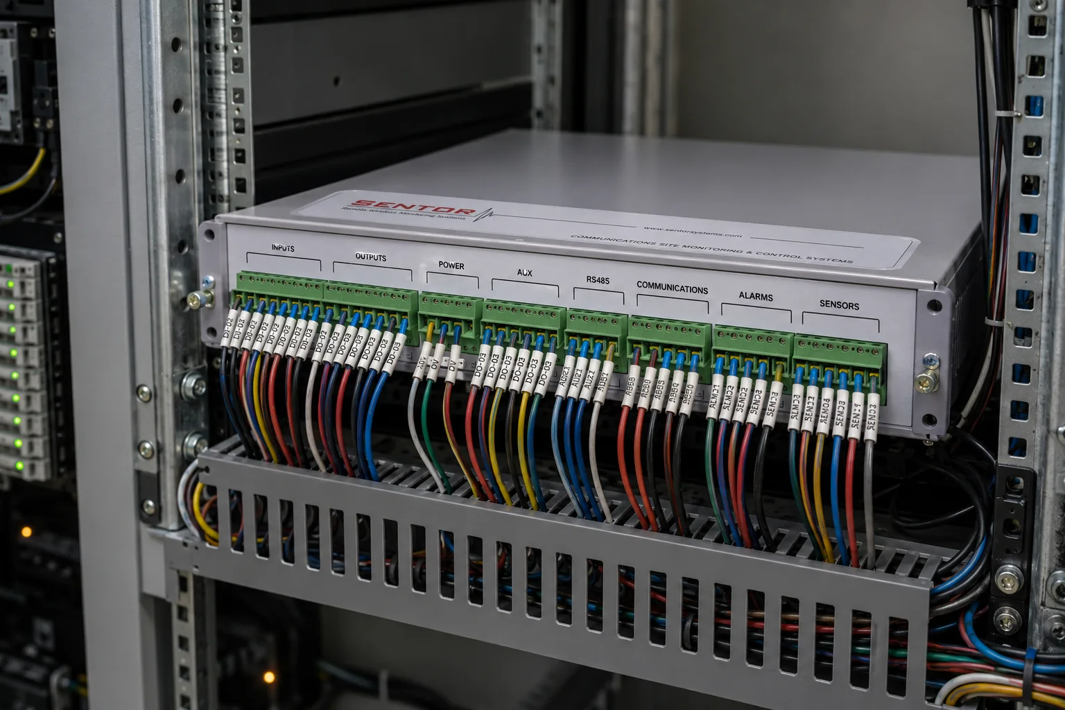
Current generation
i7000 controller
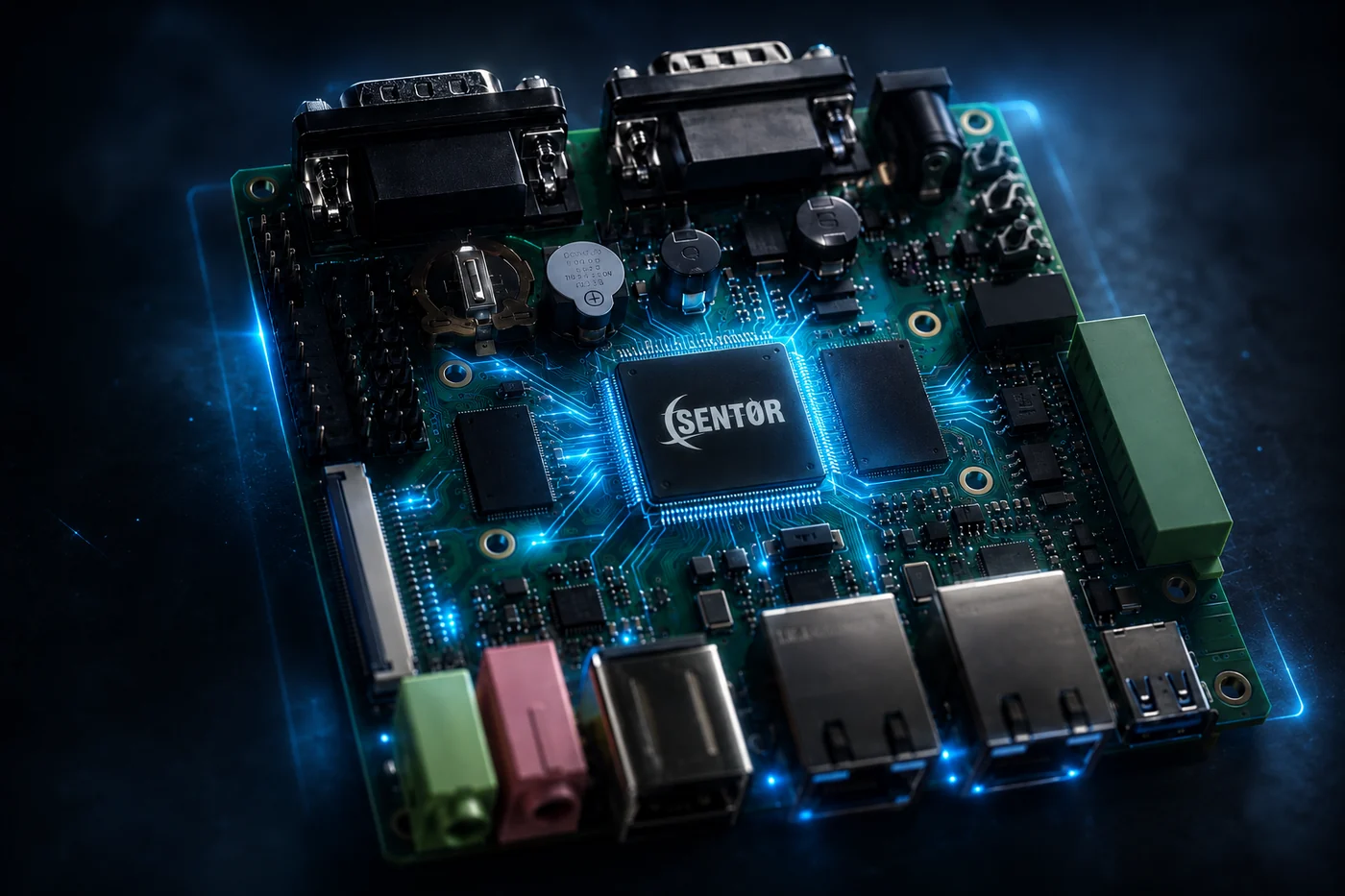
The i7000 is the controller specified for new installations. It is built on a 1 GHz ARM Cortex-A8 platform with gigabit networking on board, and it measures analogue signals at a resolution the earlier generation could not reach.
It appears as the IoT7000 in earlier Sentor literature and in our Australian distributor’s catalogue. Same controller, same part — if you are working from an older quotation or datasheet under that name, it is this one.
| Specification | Detail |
|---|---|
| Analogue inputs | 8 channels, 0 to 65 V in a single range — no range switching or link selection |
| Analogue resolution | 1 mV; 20 µA on a 4–20 mA current loop |
| Analogue outputs | 2 channels, 4–20 mA |
| Digital inputs | 8 channels, opto-isolated |
| Relay outputs | 8 channels, normally-open and normally-closed contacts, 1 A rating, with pulsed and timed on/off operation |
| Processor | 1 GHz ARM Cortex-A8 (Texas Instruments Sitara AM3358) |
| Memory | 512 MB DDR3 SDRAM and 512 MB NAND flash |
| Ethernet | 2 × 10/100/1000 Mbps, RJ45 |
| Fieldbus | CAN 2.0 and RS-485 |
| Serial | 2 × RS-232 (DB9), plus TTL-level serial on expansion headers |
| USB | 2 × USB 2.0 host, 1 × USB 2.0 OTG |
| Board | 96 mm × 96 mm, 6-layer PCB |
| Supply | +12 V |
| Operating temperature | 0 °C to 70 °C |
| Operating humidity | 20% to 90% |
The i7000 is built on a single-board computer platform that also carries display, audio and peripheral interfaces. Those are properties of the board rather than of the monitoring product, and are not listed here. Ask us if a particular interface matters for your application.
Choosing between them
i7000 and ST3000 side by side
Both generations are supported. The practical differences are the analogue front end, the addition of analogue outputs, and how the controller gets onto a network.
| ST3000 — earlier generation | i7000 — current | |
|---|---|---|
| Analogue input range | 0–1 V, 0–5 V, 0–10 V, 0–30 V, 4–20 mA | 0–65 V in a single range, plus 4–20 mA |
| Analogue resolution | Better than 0.5% accuracy | 1 mV, and 20 µA on current loops |
| Analogue outputs | None | 2 channels, 4–20 mA |
| Base I/O | 16 inputs, 8 relay outputs | 8 analogue in, 8 digital in, 8 relay out, 2 analogue out |
| Expansion | To 80 inputs and 40 outputs with ST317 cards | Confirm with us for your site |
| Network | Serial-to-ethernet module (ST301 / ST1100) | 2 × gigabit ethernet on board |
| Fieldbus | RS-485, X10, C-Bus | RS-485 and CAN 2.0 |
| Operating temperature | 0 °C to 50 °C | 0 °C to 70 °C |
| Status | Earlier generation, fully supported | Current generation, specified for new installations |
Three things worth knowing. The i7000 reads 0–65 V on one input without range selection, which covers 12 V, 24 V and ±48 V telecom supplies on the same channel. Its two 4–20 mA outputs mean it can drive a control loop rather than only switch a relay. And CAN 2.0 opens up engine and generator data that a contact closure cannot carry.
Earlier generation
ST3000 controller — full specification
The ST3000 family remains in service and remains supported. Expansion cards, communications modules, keypads and sensors are still available for installed sites, and the specification below is the published one for that platform.
Inputs
| Specification | Detail |
|---|---|
| Base inputs | 16 — 8 digital clean-contact optically isolated, plus 8 general-purpose programmable as analogue or digital |
| Maximum inputs | 80 per controller, using ST317 expansion cards |
| Analogue ranges | 0–1 V, 0–5 V, 0–10 V, 0–30 V, and 4–20 mA current loop |
| Other input modes | Clean-contact digital, protected loop with double 10k end-of-line resistors, linear and non-linear analogue, direct temperature sensor (°C or °F) |
| Sample rate | Up to 20 times per second |
| Analogue accuracy | Better than 0.5% |
Outputs
| Specification | Detail |
|---|---|
| Base outputs | 8 SPCO (single-pole double-throw) relay contact closures |
| Relay rating | 1 A maximum switching. Maximum voltage 24 VDC / 24 VAC where UL approval is required, or 48 VDC / 32 VAC where it is not. |
| Output terminals | Each output presents a numbered common terminal plus normally-closed and normally-open contacts |
| Input terminals | 16 inputs as numbered pairs (1A–8A, 1B–8B). The A terminal carries a pull-up for unpowered inputs — switches, protected loops and thermistors; the B terminal floats, for analogue voltage and current. |
| Auxiliary rails | Aux 1 and Aux 2 at 12 V. Aux 1 is held up by the backup battery through a mains failure; Aux 2 is not. |
| Maximum outputs | 40 per controller, expanded in groups of 8 by ST317 cards |
| Dedicated outputs | Security strobe and siren outputs |
| Auxiliary power | Approximately 800 mA at 12 VDC for powering remote sensors, reducing to approximately 500 mA when an ST317 is fitted |
Communications
| Specification | Detail |
|---|---|
| Serial ports | 2 × RS-232 and 2 × RS-485 per controller |
| Multi-controller | RS-485 links multiple controllers together on one site |
| Keypad terminals | Up to 31 LCD RS-485 four-line keypads (32 addresses) per the published specification — confirm with us for your controller generation |
| Keypad cable run | Up to 1,200 m on four-wire cable, shielded cable recommended |
| Dial-up modem | Hayes-compatible landline, up to 19.2k baud |
| Voice / DTMF card | ST330, 2400 baud, with dial-up, voice and DTMF recognition |
| RF modem | ST303 radio modem, 2400 baud |
| Network and cellular | ST301 / ST1100 serial-to-ethernet, and the ST30G multi-band cellular modem with static IP |
| Transmission media | Cellular, wireless, satellite, telephone, microwave and fibre optic |
| Building interfaces | X10 power-line carrier and Clipsal C-Bus lighting control |
Access control
| Specification | Detail |
|---|---|
| Reader standard | Wiegand, supporting up to 64,000 users through the ST352A |
| Reader types | Card, proximity, keychain medallion, fingerprint, palmprint, iris and facial recognition |
| Interoperability | Cardax, Axeze, Wiegand, Variprox and others on request |
| Card storage | Card codes are held in the controller, so access keeps working when a site is offline |
Power
| Specification | Detail |
|---|---|
| Supply | 16 V ±10% AC from an externally mounted 240/110 V transformer rated 16 VAC at 3 A (ST390 power supply) |
| Current draw | 250 mA with no load connected and no outputs energised; 350 mA with all output relays energised |
| Battery backup | Optional 7.2 Ah 12 V sealed lead-acid battery with an on-board charger. Most sites run the controller from the site’s existing battery bank and monitor that bank as a device in its own right. |
| Memory retention | On-board lithium battery-backed memory |
Physical & environmental
| Specification | Detail |
|---|---|
| Housings | Lockable 19″ rack (2 RU), wall-mount cabinet, reinforced security housing, or IP65 watertight enclosure |
| Front panel | 19 inch (483 mm) wide × 3 7/16 inch (88 mm) high |
| Case | 17 1/8 inch (436 mm) W × 3 1/8 inch (80 mm) H × 13 3/4 inch (350 mm) D |
| Cable entry | 7 knockout blocks in the rear panel, 3 in the back plane, optional 9-pin D connector for RS-232 |
| Operating temperature | 0 °C to 50 °C |
| Operating humidity | 5–95% relative humidity |
| Tamper | Optional tamper switch, activated on removal of the unit |
Logic & logging
| Specification | Detail |
|---|---|
| On-site logic | Scenario programming written in plain English statements, stored on the controller and executed independently of any connection |
| Event log | Full on-board event log with time and date stamp; log size is user-definable |
| Programming variables | Definable internal flags, classes, thermistors, variables and counters |
| Real-time clock | Accurate to 2 seconds per day or better, with a settable correction factor |
Commercial
| Specification | Detail |
|---|---|
| Warranty | 12 months from purchase, guaranteed to operate reliably to the published specifications. Service on a return-to-reseller basis, limited to the original purchase cost of the unit. |
| Extended warranty | Available depending on system design and equipment used. |
Sizing a site
The three numbers people actually need
Point count
Count every reading and every switched item at the site, then add the ones you will want in two years. Sixteen inputs and eight outputs come as standard; each ST317 adds sixteen and eight, up to eighty and forty.
Fitting more than two expansion cards needs the ST450 ribbon cable, which is supplied with the card. With an ST330 telephone card fitted, three expansion cards is the maximum.
Power budget
The controller draws 250 mA with nothing energised and 350 mA with all relays energised. Sensors drawing from the auxiliary supply add to that, up to approximately 800 mA at 12 VDC.
On a solar or battery-backed site, that draw against your battery capacity is what determines runtime. Tell us the bank you have and we will work it out with you rather than quote a figure that does not match your site.
How it reports
The bearer is chosen per site, and different sites on one network can differ. Cellular, ethernet, radio, satellite, microwave, fibre and dial-up are all supported.
Whatever the link, scenario logic runs on the controller. The connection determines how quickly you hear about an event, not whether the site handles it.
About these figures. Every specification on this page is taken from Sentor’s own published technical specification sheet and product documentation. Specifications for a particular configuration should be confirmed with us before you commit to a tender or a purchase order — ask and we will send the current documentation for the exact configuration you are specifying.
Specifying a system against a requirement?
Send us the point list and the site conditions. We will tell you what configuration covers it, and what it does not.